Flexible Circuit Board
A flexible circuit board (PCB) is a type of printed circuit board that can be shaped into various designs and sizes. It contains conductive metal strips, usually copper, that are insulated by a dielectric material to form a complete electrical path. These conductive paths allow flex PCBs to carry signals even while they are bent or moved, which is necessary for many applications. They also protect against electromagnetic interference (EMI) from adjacent components and wires. The benefits of using a flex circuit include lower assembly costs, reduced wiring errors, and greater design flexibility.
Flex circuits come in a wide range of thicknesses, materials, and finishes to meet the needs of specific applications. They can be fabricated with either single-sided or double-sided conductor layers. The choice of which to use depends on the physical environment, mechanical strength, and cost considerations. The base layer of a flex circuit is typically a thin, flexible polymer film. Polyimide is a popular choice, as it is very tough and tolerant of manufacturing processes and product assembly. It is also very heat resistant and offers excellent thermal stability.
A flexible circuit board is often finished with a layer of solder mask, which insulates the conductors and prevents them from corroding. It can also be coated with silkscreen and plated with gold to improve its appearance and performance. These coatings and finishes can add to the overall price of a flex circuit, but they are important for ensuring a high-quality final product.
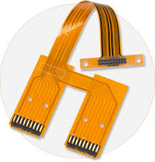
What Is a Flexible Circuit Board?
The base film of a flex circuit is important because it provides most of the circuit’s primary physical and electrical properties. For a typical circuit, this is a thin film of polyimide or epoxy resin that is used to bond the conductive copper layer. Unlike rigid PCBs, which have an entire network of solder-mounted components, a flex circuit has just one copper layer that is bonded to the substrate with an adhesive.
Another common feature of a flex circuit is the copper trace. Because it is so close to the soldered connections, it can cause failures if the traces are not properly designed. For this reason, it’s important to stagger the traces or leave a space between them. This allows the traces to stretch more before fatigue cracking or delamination occurs.
Other important factors to consider when designing a flex circuit are the type of flex material and the number of layers. A thin PI or PET film is a common option for the base layer, while an epoxy or glass fiber core is typically used as the center of the circuit. Both PI and PET are available in different thicknesses, which can affect the overall cost of a flex circuit. It’s also important to specify the exact materials and laminate options during the design process, as these can affect the fabrication price. The final cost of a flex circuit will depend on the raw materials, fabrication techniques, and quality control steps performed by the manufacturer.