Flex Circuit Boards Reduce Assembly Time
In the internet of things (IoT) era, flex circuit boards are used in a multitude of different devices. They are able to handle complex electronics and sensors in compact, space efficient packages. With their inherent flexibility, flex circuits reduce assembly time and costs by eliminating the need to hand-build wire harnesses. They also provide more opportunities to reduce the size and weight of the device by integrating form, fit and function.
Using a rigid-flex PCB with integrated stiffeners can help mitigate any bending that might occur during the assembly process. It can be especially important in applications that require a large amount of movement, such as a vehicle dashboard or aircraft panel. Stiffeners are typically made of a rigid material like FR4 or metal and are laminated onto a flex circuit. They can be positioned where needed, such as the edge connector or mounting holes.
While most flex PCBs are manufactured from copper, it is possible to have a rigid-flex board with an alternative conductive material such as aluminum or gold. Choosing the right materials is crucial to the integrity of the finished product. A key factor is the thickness of the conductive layer. Thicker foils can be harder to etch, but they are more resilient against fatigue and stress cracking. The choice of foil type is also critical. Using higher-grade rolled annealed (RA) copper is an excellent option for flex circuits that will be subject to repetitive bending and movement. RA copper is a little more expensive, but it can stretch much longer before fatigue cracking occurs.
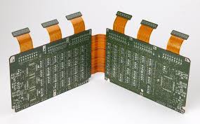
How Do Flex Circuit Boards Reduce Assembly Time?
Another major factor in the reliability of a flex circuit is the pre-bake that must be performed before assembly. Both flexible and rigid-flex circuits are hydroscopic up to 2-3% by weight and require a thorough pre-bake before soldering. Failure to perform this step can cause coverlay delamination, layer-to-layer delamination and stiffener delamination. The reason for this is that entrapped moisture will boil at soldering temperatures and vaporize, causing delamination.
The time required for the pre-bake varies depending on the thickness of the flex stack-up, layers, buried and blind vias, copper ground planes and room/area conditions (%RH). It is recommended that all flex and rigid-flex circuits be pre-baked prior to hand, wave or IR soldering.
Another way flex circuits reduce assembly time is by eliminating routing errors. With accurate designs and automated production, flex circuits only route to points called for in the schematic, net list or gerber files. This significantly reduces assembly error and production time. It also helps to minimize the cost of reworking components or scrapping a complete board due to a mistake during assembly. Ultimately, combining rigid and flex PCBs in a design can result in significant improvements in assembly times and manufacturing costs. If you’re ready to learn more about the benefits of incorporating a flex circuit into your next project, contact an experienced flex PCB manufacturer today. They’ll be happy to answer any questions you may have!